Distillation simulation with close boiling points of components using Aspen HYSYS
 |
| Distillation Column |
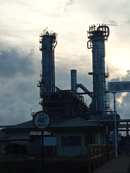
Distillation is one of the most important operations in the separation process in the oil industry. Distillation separates components in a mixture based on the difference in boiling points between the components to be separated. Binary or multi-component mixtures can be separated using distillation. The nature of the feed and the desired product determine variables such as column pressure, temperature, column diameter, and size.
Main components of a distillation column
Each component is
used to enhance material transfer and thermal energy transfer. Generally,
distillation consists of the following components:
- Vertical shall be where the separation of
liquid components takes place
- Column internals such as plates,
trays, or
packing used to enhance component separation
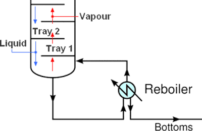
- Reboiler to provide the
evaporation required for the distillation process, this page describes
the reboiler as the largest energy consumer in distillation.
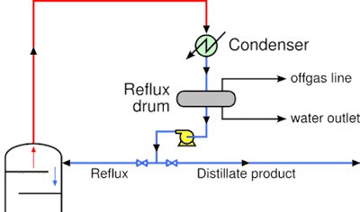
- Condenser to cool and condense the
vapor that leaves the top of the column
- Reflux drum to collect condensed
vapor from the top of the column so that the liquid (reflux) can be recycled
back into the column.
The feed in the
form of a liquid mixture is usually inserted near the center of the column on a
tray known as the feed tray. The feed tray divides the distillation column into
enriching (top) and stripping (bottom). The feed flows to the bottom of the
column and is collected at the bottom side of the reboiler. Heat is supplied to
the reboiler to produce vapor. The heat source in some chemical plants is
usually steam. The vapor produced in the reboiler is fed back to the bottom of
the distillation column. The liquid that comes out of the reboiler is called
the bottoms product.
The vapor rises to
the top of the column and enters the top of the column, the vapor is then
cooled with a condenser. The condensed liquid is collected in a vessel called
the reflux drum. This liquid is partially recycled back to the top of the
column or referred to as reflux. The remaining liquid that is not recycled is
referred to as distillate or top product.
The basis for simulating a distillation column is phase equilibrium,
specifically vapor-liquid equilibrium. Distillation separates components from
liquid mixtures using selective boiling and condensation. Understanding
vapor-liquid equilibrium is essential for the design, analysis, and control of
distillation columns. We have previously discussed vapor-liquid equilibrium on this
page.
To better understand how to simulate a distillation column, below we
present an example case that can be used as an exercise to simulate in Aspen
HYSYS.
Background
Ethylene is an important monomer and is made from ethane. The reaction conversion is not perfect, so ethylene must be separated from the system. Ethane and ethylene are molecularly similar, and so are difficult to separate. The difficulty of separation is compounded by the fact that polymer production requires very pure raw materials.
Aspen HYSYS problem and solution
A stream containing 68.5wt% ethylene with a total flow rate of 7.3
million lb/day was fed into a distillation column consisting of 125 stages. It
is desired to produce a distillate product stream containing at least 99.96 wt%
ethylene with a total flow rate of 5 million lb/day. It is also desirable that
the bottom of the product contains no more than 0.10wt% ethylene. Determine if
this separation is feasible.
Assumptions:
- 100% tray efficiency
- Total condenser
- Column operating pressure 300 psig
- Refrigerant utility stream capable of condensing the ethylene mixture
(not included in the model)
- Feed mixture is at 350 psig and is a vapor
- 125 stages
- Feed enters the column at stage 90
- Peng-Robinson equation of state
Open Aspen HYSYS and select New to start a new simulation.
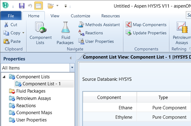
Create a component list by clicking the Component List folder,
then click Add to add a new component list. Select Ethane and Ethylene
to add to the component list. You may need to use the search function by typing
in ethene and pressing enter to find the component ethylene.
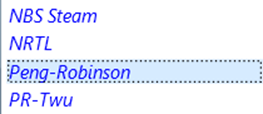
Define the Fluid Package used by clicking on the Fluid Packages
folder and selecting Add to add a new fluid package. Select Peng-Robinson
as the package property. The Peng-Robinson equation is usually used to model
systems containing hydrocarbons at high pressure.
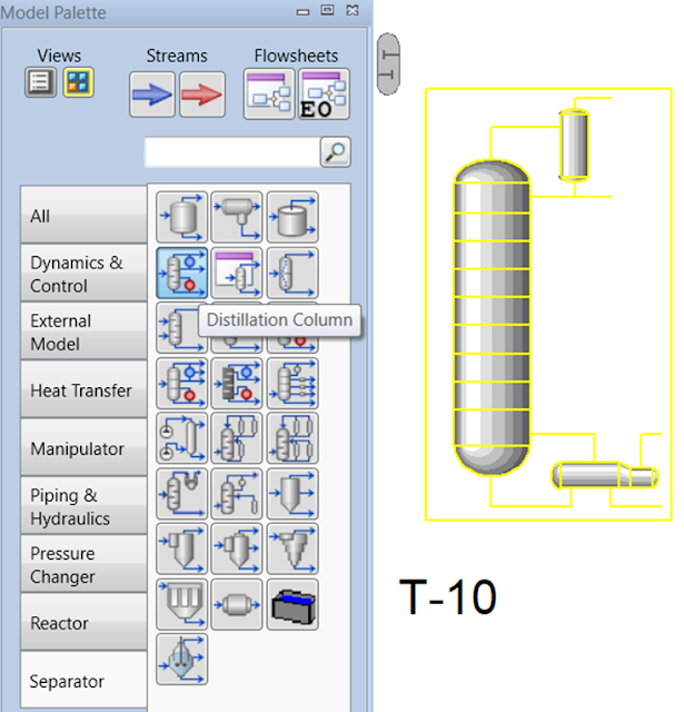
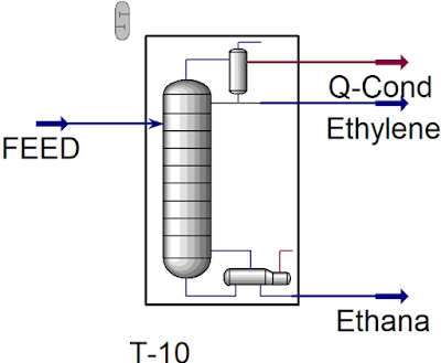
Now we can start the simulation. Click on Simulation at the bottom left of the screen. In the flowsheet enter the Distillation Column located in the Separator tab of the Model Palette.
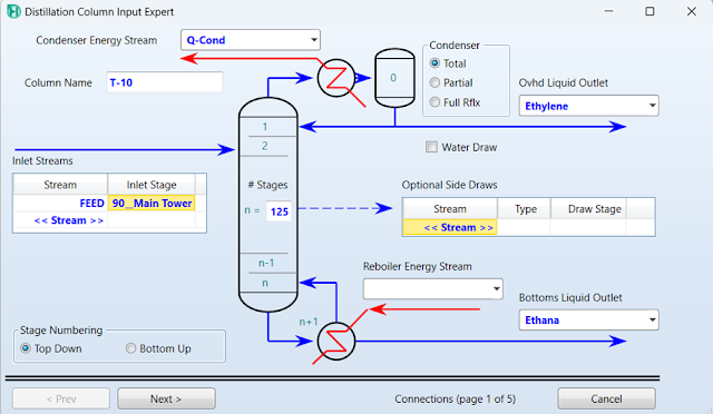
Double-click on the Distillation unit (T-10) and the Distillation
Column Input Expert window will appear. Here we will create the feed stream
as well as the product stream, and define the column operating conditions. On
the first page, enter 125 for # Stages and specify the feed and
product streams as shown below.
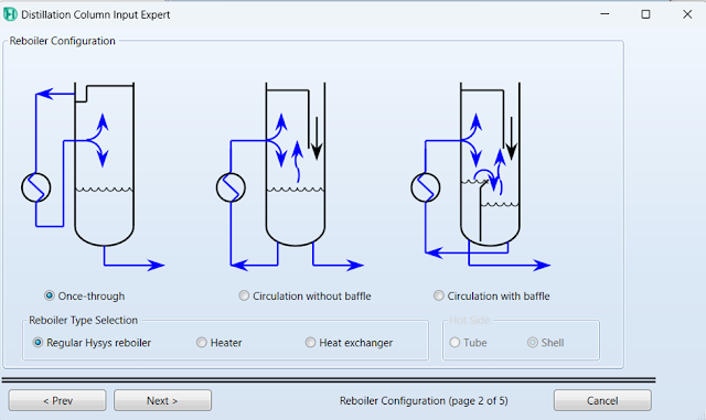
Click Next and page 2 will appear. Select Regular Hysys Reboiler
for Reboiler Type Selection, and select the Once-through radio
button. Click Next.
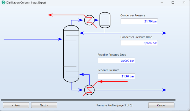
Enter the condenser and reboiler pressures of 300 psig (21,70 bar)
each. This indicates no pressure drop through the acceptable column for this
simple example.
Click Next, on this page (page 4 of 5) you can enter the
estimated temperatures for the condenser, upper stage, and reboiler. This page
can also be left blank without filling in the requested temperature parameters
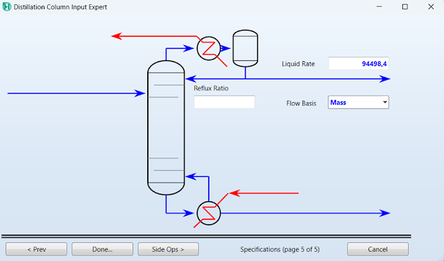
by clicking Next. On the last page, you can enter the liquid distillate
rate or reflux rate. From the example case above, we know that the distillate
rate is 5 million lb/day of ethylene. Select Mass for Flow Basis
and enter 5000000 lb/day (94498.4 kg/hr) for Liquid Rate. Select Done
to enter the column properties window.
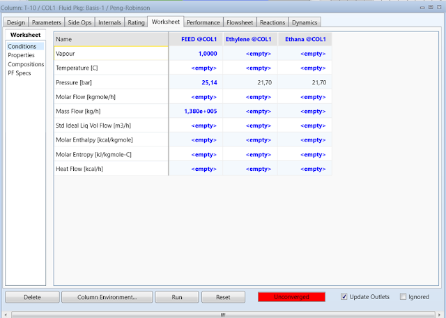
The first step is to define the feed stream entering the column. In the Column
Properties window, go to the Worksheet tab. In the Conditions form,
enter a pressure of 350 psig (25,14 bar), a Vapor fraction of 1,
and a Mass Flow of 7.3e+06 lb/day (1,380e+005 kg/hr) for the Feed@COL1
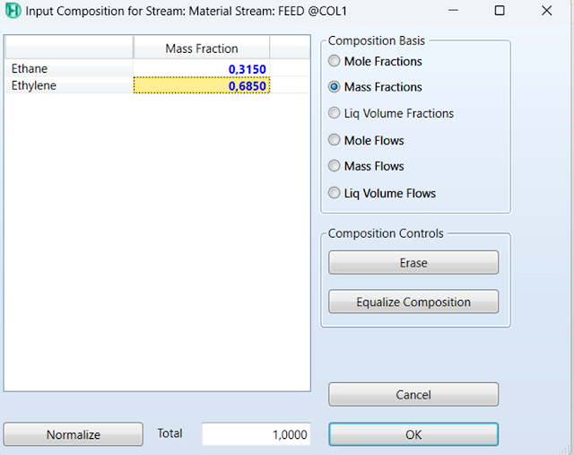
flow. Go to Compositions Sheet in the Worksheet tab. Here we
will define the composition of the feed stream. Type a number into the Feed composition
grid for Ethane to open the Input Composition for Stream window. Select the Mass
Fractions radio button, and enter 0.315 for Ethane and 0.685
for Ethylene. Click OK. The feed stream on the main flow sheet will
turn blue, indicating that all required inputs have been entered and that it
has been solved for all properties. If you open the Feed stream property window
you will see a green status bar saying OK at the bottom.
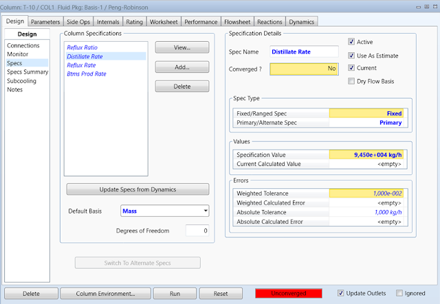
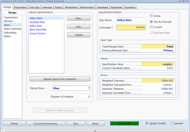
Now we have to enter the design specifications to achieve the desired
product composition as provided in the problem statement. In the Column
property window, open Design | Specs. Our two design specifications for
this simulation are the distillate rate and the mass fraction of ethylene in
the underflow. In the specification column, there should already be a Distillate
Rate specification created from the expert input column. Ensure that the
distillate specification value is correct (9.450e+004 kg/hr) and that the spec
is checked as active.
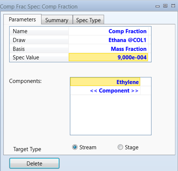
On the Column Specification form, click Add and select the
Column Component Fraction specification. In the Comp Frac Spec
window select the Stream radio button for Target Type. Enter Ethane@COL1
for Draw, Mass Fraction for Basis, and 9.0e-004 for
Spec Value. Select Ethylene for the Component. Close Close
this form when all information has been entered.
Make sure this specification (Comp Fraction) is checked as Active
in the Specification Details area. You will notice that after
enabling the Comp Fraction specification, the Degrees of Freedom
change to -1. This means that the problem is over-specification. To fix this,
simply disable one of the column specifications, in this case, the Reflux
Ratio. Once the reflux ratio design specification is disabled, the column
should resolve. You will notice that the status bar at the bottom of the sheet
will turn green and say Converged.
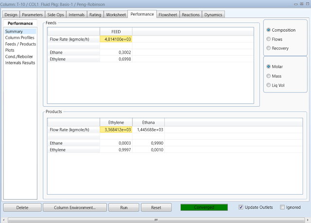
Checking results. On the Column properties window, go to the Performance
tab. On your Summary sheet, you can see the flow rate and composition of
the feed and product streams. You can see that both specifications described in
the problem statement are met.
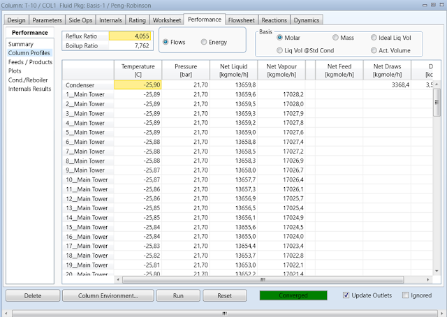
On the Column Profile sheet, you can see the calculated reflux
ratio, boiling ratio, and material and energy profile through the column.
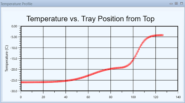
On the Plots sheet, you can create plots such as temperature and
composition along the column, as shown below.
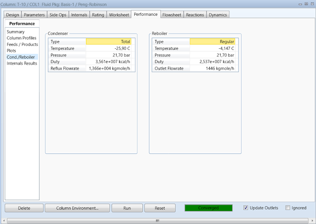
Finally, on the Cond./Reboiler sheet you can see the calculated operating conditions for both the condenser and reboiler.
Conclusion
The 125-stage column was able to exceed the specification of 99.96wt%
ethylene at 5 million lb/day, as well as the bottom had less than 0.10wt%
ethylene. It can therefore be concluded that this column is capable of
completing the desired separation. Aspen HYSYS allows engineers to model
existing equipment and see if it is possible to reuse it or, if not, design new
equipment that will meet very specific criteria.

