The heat of vaporization simulation using Aspen HYSYS
Hi chemical
engineering friends, we are back again with a new discussion which is certainly
quite interesting. This time we discuss the Heat of Vaporization, its
application in industrial equipment, and how to simulate it on Aspen HYSYS. Don't know, don't love, is a
term that refers to us knowing an object first before we have direct contact
with it. Yes... it is good before we simulate it we first understand how the
concept of heat of vaporization occurs.
Introduction
The process of a
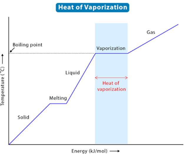
liquid changing its form to a gas is known as boiling, and the temperature at
which it occurs is called the boiling point. Vaporization occurs because of the
heat due to endothermic processes added to a substance. The heat of Vaporization,
often called enthalpy of vaporization or latent heat of vaporization, is the
amount of energy required for a liquid to transition to its gas phase. For a liquid to vaporize,
a certain amount of heat is required for the substance to change phase.
Latent heat is not
related to temperature changes but only phase changes. The latent heat of
vaporization requires heat to change the material from the liquid phase to the
vapor phase at a fixed temperature and pressure. The process of vaporization
requires a large amount of energy to allow the liquid particles to overcome the
scorching forces between molecules until vaporization occurs. The heat of
vaporization formula can be seen below:
Where,
Hv = Heat of
Vaporization
M = Mass of
Substance
Q = Heat
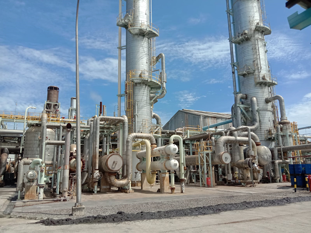
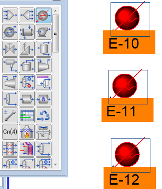
This time we will simulate industrial equipment that uses the principle of the heat of vaporization, namely a Reboiler. Below is an example case that we can simulate with Aspen HYSYS.
Case example
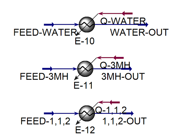
A reboiler is used in conjunction with a distillation column to vaporize the bottom product of the distillation column. The reboiler provides the heat required for vaporization. The main driving force for distillation is energy. The reboiler consumes the most energy from the distillation column. The basic principle of a boiler is to vaporize material in a reboiler causing steam to flow from the bottom of the column to the top of the column. The amount of energy required is determined by the heat of vaporization. Therefore, it is important to know the heat of vaporization of various species during solvent selection if the conditions of the mixture to be distilled are azeotropic. With everything else being equal, we should select components with lower heat of vaporization so that we can achieve the same degree of separation with less energy. The example below consists of three isolated heater blocks. Each heater block is used to calculate the heat of vaporization for each of its components.
Simulation completion
Create a new
simulation in Aspen HYSYS
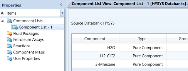
Enter the Component
List by opening the Component List folder and selecting Add. Select
Water, 3-methyl hexane, and 1,1,2-trichloroethane.
Define the Fluid
Packages used, and select Add. Then select UNIQUAC and select RK as Vapor Model.
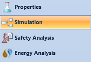
Next, enter the
simulation by clicking Simulation on the bottom left screen.
Add Heater blocks to the flowsheet
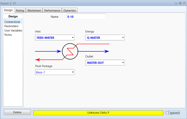
Double-click on E-10 to open the property
page. The first heater will be used to vaporize water. Define the Inlet flow as
FEED-WATER, Outlet flow as WATER-OUT, and Energy flow as Q-WATER.
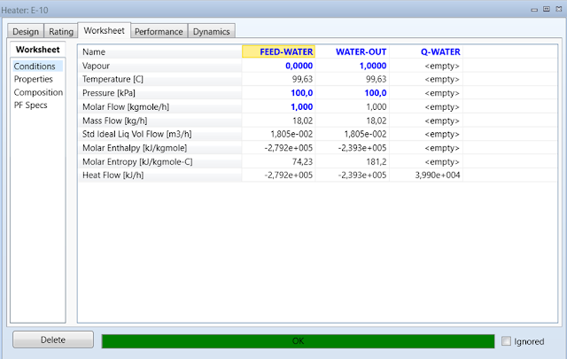
Click the Worksheet
tab. Enter the Pressure and Vapor Fraction values of the FEED-WATER
stream as 100 kPa and 0
respectively with a Molar Flow of 1 kgmole/h. In the Composition
sheet under the Worksheet tab enter a Mole Fraction value of 1
for Water in the feed stream. The last step is to enter the Pressure
and Vapor Fraction values for the WATER-OUT stream of 100 kPa and 1
respectively. The heater will calculate the energy requirement needed to
evaporate the water. Record the Heat Flow of the Q-WATER energy
stream.
We use the same
steps for heaters E-11 and E-12 which will vaporize
3-methylhexane and 1,1,2-trichloroethane.
Double-click on E-11 to open the property
page. The second heater will be used to vaporize 3MH. Define the Inlet flow as FEED-3MH,
the Outlet flow as 3MH-OUT, and the Energy stream as Q-3MH.
Click the Worksheet tab. Enter the Pressure
and Vapor Fraction values of the FEED-3MH flow as 100 kPa and 0 respectively with a Molar
Flow of 1 kgmole/h. In the Composition sheet under the Worksheet
tab enter a Mole Fraction value of 1 for 3methylhexane in the
feed stream. The last step is to enter the Pressure and Vapor
Fraction values for the 3MH-OUT flow of 100 kPa and 1
respectively. The heater will calculate the energy requirements needed to
vaporize 3MH. Record the Heat Flow of the Q-3MH energy flow.
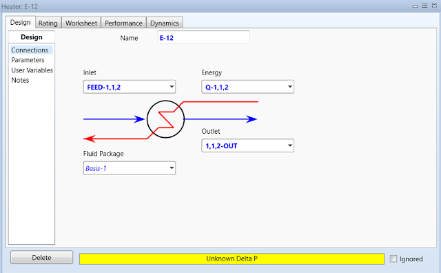
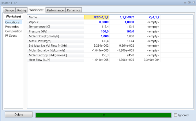
Double-click on E-12 to open the property
page. The third heater will be used to vaporize 1,1,2-trichloroethane. Define
Inlet flow as FEED-1,1,2, Outlet flow as 1,1,2-OUT, and Energy
flow as Q-1,1,2.
Click the Worksheet tab. Enter Pressure
and Vapor Fraction values for FEED-1,1,2 streams of 100 kPa and 0 respectively with a Molar Flow of 1 kgmole/h. In the Composition sheet under the Worksheet
tab enter the Mole Fraction value of 1 for 1,1,2-trichloroethane
in the feed stream. The last step is to enter the Pressure and Vapor
Fraction values for the 1,1,2-OUT stream of 100 kPa and 1
respectively. The heater will calculate the energy requirement needed to
vaporize 1,1,2. Record the Heat Flow of the energy
stream Q-1,1,2.
Conclusion
Water = 39895,2948508865
KJ/h
3-methyl hexane = 30520,2548025187 KJ/h
1,1,2-trichloroethane = 33491,3492618545 KJ/h
Although water
has a small molecular weight, its heat of vaporization is large. The heat of
vaporization for water is about 18% higher than 1,1,2-trichloroethane
and about 30% higher than 3-methyl
hexane. Of the three options, 3-methyl hexane has
the lowest heat of vaporization and will require the least energy as an insolvent distillate.
If you find this blog useful, please share it with your social media colleagues, so that other chemical engineering colleagues also feel the same benefits from this blog.

