Refrigerant system simulation using Aspen HYSYS
The refrigeration
system simply works by regulating the pressure and also the temperature of the refrigerant. To simulate
the working mechanism of this refrigerant system, we can do it with the help of
Aspen HYSYS. But before going further to simulate it, we need to know first how
the working principle of the refrigerant system. Therefore, we need to get
acquainted with this refrigerant system.
Introduction
Refrigeration
systems are often encountered in our daily activities, a simple example is the
use of Air Conditioner (AC). In the case of an Air Conditioner (AC), the refrigeration system
uses refrigerant to extract heat from the process circulation fluid and then
discharges it into the atmosphere. The basic principle of a refrigerant system
is the compression and phase change of the refrigerant from gas to liquid and
back again to gas. The repetitive process of changing the refrigerant from gas
to liquid and then back again to gas is called the refrigeration cycle. Changing the
physical state of a compound (from gas to liquid or vice versa) is the most
efficient method of absorbing or expanding energy.
The four main
components in the refrigeration cycle are the evaporator, compressor, condenser, and expansion valve.
1. Evaporator
Is a device that
transfers heat from the process fluid to the refrigerant which causes a phase
change (evaporation).
2. Compressor
The compressor is
the core component of the refrigerant system that works by heating the refrigerant gas causing
the pressure and temperature of the refrigerant gas to increase and then
circulating it through the process refrigerant system. Increased refrigerant gas pressure also has an impact on
increasing its temperature.
3. Condenser
The condenser lowers
the temperature of the refrigerant gas vapor to condense into a saturated
liquid, aka condensation. As a result of condensation, the refrigerant becomes
a high-pressure, low-temperature liquid.
4. Expansion valve
The expansion valve
works by lowering the pressure of the liquid refrigerant. As a result of this
pressure drop, it also has an impact on the decrease in refrigerant
temperature. Refrigerant becomes low pressure and low temperature At the
expansion valve
For the refrigeration system to work properly there must be four main components. An example of the direct application of the use of refrigerant systems in industry is the ammonia industry. In the ammonia industry, the refrigerant system is used to increase ammonia products.
 |
| Refrigerant system in ammonia plant |
Case example and simulation solution
Determine the cooling capacity of 300 kgmole/h of CFH2-CF3 when allowed to expand from 10 bar to 1 bar.
Create a new
simulation in Aspen HYSY
Enter the Component
list by opening the Component Lists folder select Add. Add 1,1,1,2-tetrafluoromethane to the component list.
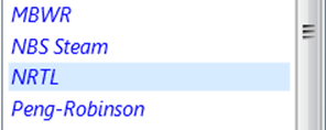
Define the Fluid Package used, and select Add. Then select NRTL as the property package
Add Compressor,
Cooler, Heater, and Valve to flowsheet
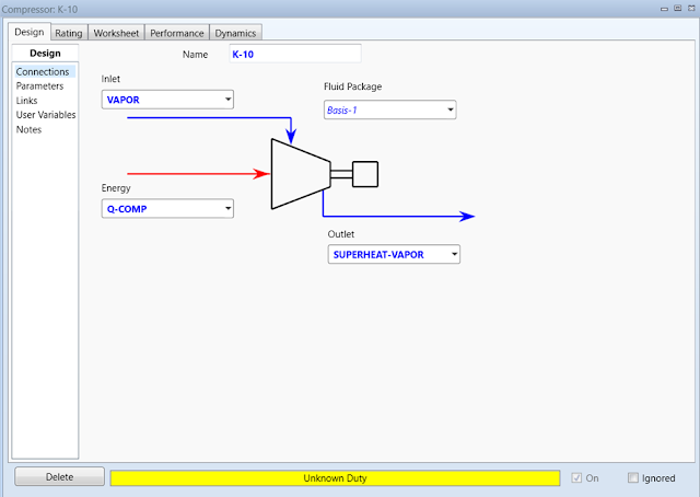
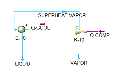
Double-click on the compressor (K-10).
Define Inlet Stream as VAPOR, Outlet as SUPERHEAT-VAPOR,
and Energy as Q-COMP.
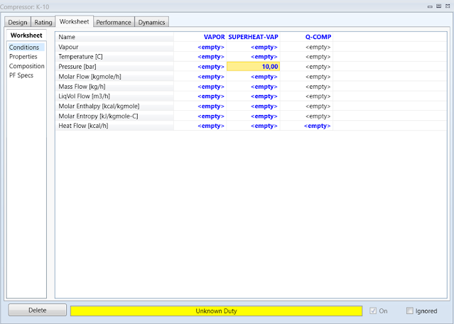
On the Worksheet
tab, enter a Pressure value of 10 bar
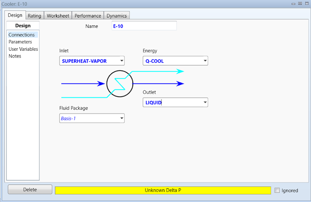
Double-click Cooler (E-10). Define Inlet Stream as SUPERHEAT-VAPOR, Outlet Stream
as LIQUID, and Energy Stream as Q-COOL.
In the Worksheet
tab, enter the outlet Temperature value of 30oC. in
the Parameter section under the Design tab enter the Delta P value = 0
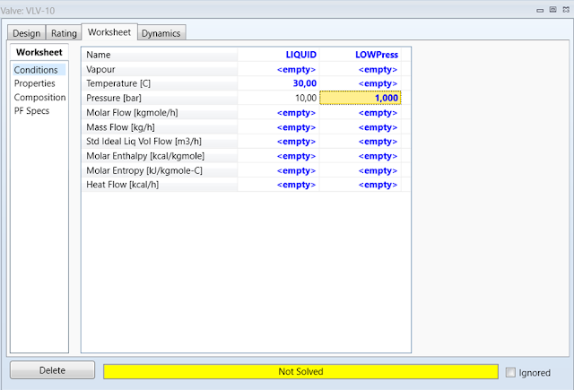
Double-click valve (VLV-10). Define Inlet
Stream as LIQUID and Outlet as LOWPress
On the Worksheet tab enter
the outlet value Pressure = 1
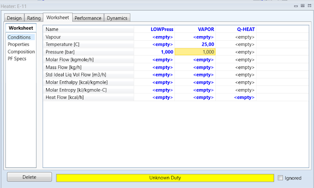
Double-click on the heater (E-11). Define Inlet Stream
as LOWPres, Outlet Stream as VAPOR, and Energy Stream
as Q-HEAT.
In the Worksheet
tab, enter the outlet Temperature value of 25oC. in
the Parameters section under the Design tab enter the Delta P
= 0
Now we have to determine the molar Stream rate and refrigerant composition. Double-click any Stream, for example, Vapor Stream. Enter a Molar Flow of 300 kgmol/hr. In the Composition form specify Mole Fraction 1 for the refrigerant.
HYSYS will complete
the calculation
Check results. To
see the cooling capacity of this refrigeration loop, double-click the Q-COOL Energy Stream. This
stream is removing 1,925e+006 kcal/hour, or about 534.72 kcal/second
Conclusion
Refrigeration is the process by which heat moves
from a cooler location to a hotter location using external work (e.g. a
compressor). We know that the vaporization of liquids requires heat. If no external heat is
available, the heat will come from the liquid itself by reducing its
temperature.
If you find this blog useful, please share it with your social media colleagues, so that other chemical engineering colleagues also feel the same benefits from this blog.


